Why Section Properties Still Decide Your Design?
Unexpected deflection, premature fatigue, failed code checks — most of these issues trace back to inaccurate section properties. The moment of inertia (I), or second moment of area, governs a structure’s resistance to bending and torsion.
It appears in the deflection formula for a cantilever beam: δ = P·L³ / (3·E·I). Under Euler buckling, the critical load P_cr = π²·E·I / (K·L)². Whether you’re designing beams, supports, or brackets, the wrong inertia value leads to costly redesigns or compliance failures.
In dynamic systems, I influence vibration modes and fatigue hotspots. For stiffened plates and offshore components, regulatory checks (AISC, Eurocode, DNV) use inertia values to assess ultimate and serviceability limit states. Simply put: if I is wrong, everything else is downstream of the error.
From Sketch to Equation: Getting the Numbers Right
Axes, Sign Conventions, and Units
Errors often start with axis confusion. Iy and Iz are taken about centroidal axes — not always horizontal/vertical in CAD sketches. Mixing units (mm vs. inches) can mislead even experienced users. Always confirm the shape’s coordinate system, and document whether inputs are in metric (mm, mm´4) or imperial (in, in´4).
Iy, Iz, Iyz, Ix (Polar) and the Move to Principal Axes (I₁/I₂)
Iy and Iz measure bending stiffness about the Y and Z axes, respectively. Iyz (product of inertia) shows coupling between axes. If Iyz ≠ 0, principal axes must be calculated by rotating the coordinate system. The polar moment Ix = Iy + Iz applies to torsional stiffness in circular/axisymmetric sections. For asymmetric or open sections, compute I₁ and I₂ (principal moments) to understand real behavior.
Elastic vs. Plastic Section Modulus (Z vs. S)
Elastic section modulus Z = I/c is used in most code checks. Plastic modulus S accounts for full plastic stress distribution and governs capacity in ductile bending scenarios. Both values are necessary — Z for elastic limits, S for collapse checks. Eurocode and AISC use both depending on limit state design.
Fast Methods for Standard Shapes (and Where They Break)
Engineers can quickly estimate I for common sections:
- Rectangle: Iy = b·h³ / 12
- Circle: I = π·d⁴ / 64
- I-beam: sum flanges and web about the neutral axis
- Hollow sections: subtract inner from outer I
- Angle/L/Channel/Z: use a composite approach with the parallel axis theorem
However, errors often arise from assuming symmetry where none exists. For example, open channels twisted about their weak axis exhibit torsional warping, not captured by Iy alone. Warping constant Cw and torsional constant J are needed for full evaluation.
Worked Example: Standard I-Section
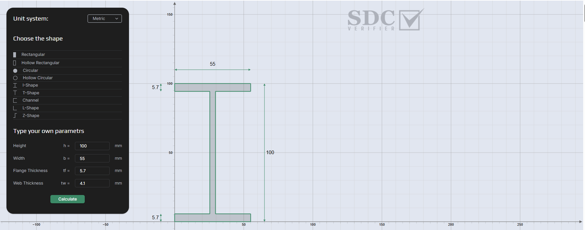
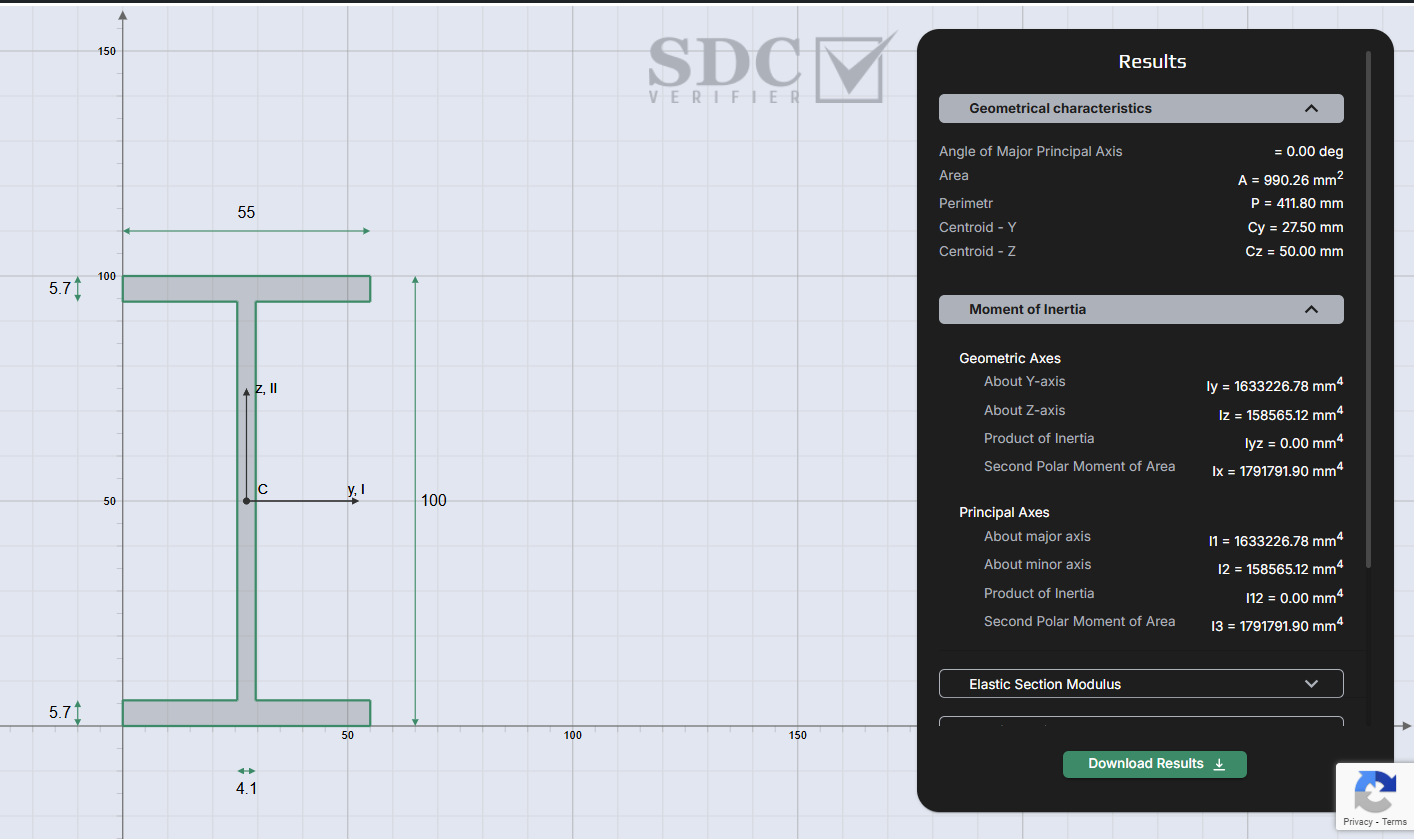
For an I-beam with height h = 100 mm, flange width b = 55 mm, flange thickness tf = 5.7 mm, web thickness tw = 4.1 mm:
- Area (A) = 990.26 mm²
- Centroid: Cy = 27.50 mm
- Moments of Inertia: Iy = 1.63×10⁶ mm⁴, Iz = 1.59×10⁵ mm⁴
- Product of Inertia: Iyz = 0 (symmetric)
- Principal I₁/I₂ = same as Iy/Iz here (no rotation)
- Zy/Zz (elastic) = 32,665 / 5,766 mm³
- Sy/Sz (plastic) = 37,609 / 8,994 mm³
- J (torsion) = 8,956 mm⁴, Cw (warping) = 3.51×10⁸ mm⁶
These values enable stiffness checks, deflection predictions, and compliance analysis.
Try It Yourself in Seconds
For fast verification, use SDC Verifier’s free moment of inertia calculator. Select metric or imperial units, pick a shape (I, T, rectangle, channel, L, Z, circular, hollow), enter dimensions, and receive instant outputs. Optionally, results can be emailed.
The tool returns:
- Geometric properties: Area, Perimeter, Centroid (Cy/Cz)
- Moment of inertia: Iy, Iz, Iyz, Ix (polar)
- Principal axes: I₁, I₂, I₃ (polar)
- Section moduli: Elastic (Zy/Zz), Plastic (Sy/Sz)
- Radius of gyration: ry, rz, rx (polar)
- Shear areas: Ay, Az
- Torsion/warping: J, Cw
This ensures accuracy in early-stage sizing or design hand-checks.
Closing the Loop in FEA: SDC Verifier in Practice
While browser tools work well for shape-level insight, engineers ultimately need property checks embedded in FEA. SDC Verifier integrates directly with Ansys, Femap, and Simcenter to extract real model geometry and compute section properties automatically. Built-in checks against AISC 360, Eurocode 3, and DNV RP-C203/RP-C201 ensure code compliance.
The software detects beam, plate, and shell elements, calculates Iy/Iz/Iyz per element, and compares analytical properties to model-based ones.
Misalignments, thickness errors, or unrealistic geometry can be flagged before finalizing reports. Engineers can run automated unity checks, fatigue analysis, or buckling curves directly inside the project.
This reduces manual transfer errors and shortens the verification cycle from hours to minutes.
Wrap-Up
Moment of inertia governs structural performance under bending, buckling, and torsion. Getting I right determines whether a design will pass code checks, stay within deflection limits, and avoid costly overdesign. From early concept to full FEA verification, accurate section properties matter at every stage.
Start with the free moment of inertia calculator to validate your cross-section properties, then bring your data into SDC Verifier for complete, standard-based verification inside your FEA model.


